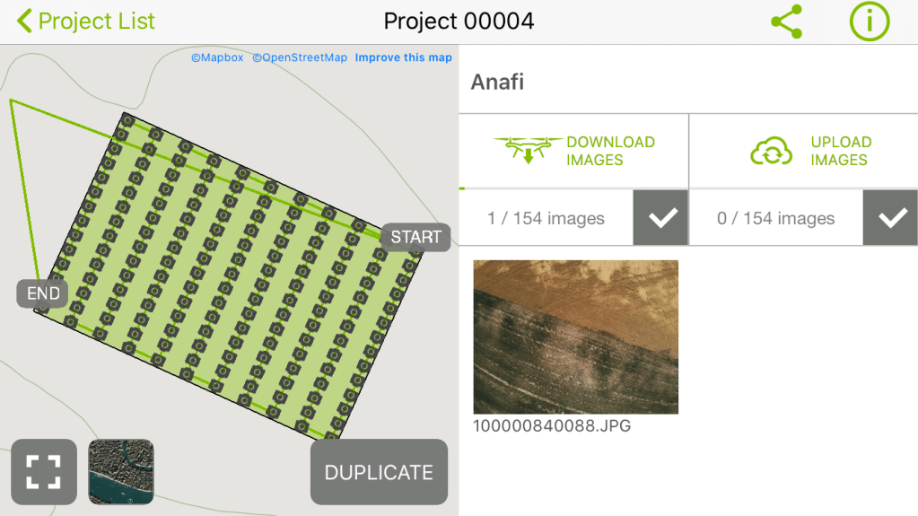
One of my previous posts was how to use Open Drone Map to create products from a UAV collection. One thing that I learned last year at the ESRIUC was how to use the Orthomapper tools in ArcGIS Pro. Recently I had the opportunity to fly my Parrot Anafi and do a data collection over a farm field. Capturing the data was fun and easy with the Anafi. I captured 154 images with about 80% overlap (which is a bit overkill) which took about 10 minutes to fly. I used Pix4D Capture for flight planning and control.
Getting started in an Orthomapper Workspace
Once I got home, I downloaded the data and started to explore what I could do with it in ArcGIS Pro. I started the Orthomapper workspace (from the imagery ribbon) and started the process.

Then I went through the workspace workflow. First, give it a name, and if you choose fill out the metadata.

Then I loaded the images. When you load the folder of images it will read the EXIF tag information and try to populate the camera information.
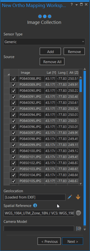
Here I found an issue because the Anafi is not in the camera database. So I had to do some digging around along with trial and error to find how to create my own camera calibration file. To figure it out, I used the EXIF data to get the focal length, which is not the same as the 35mm equivalent focal length in the EXIF. For the Anafi, the focal length is 4 mm and the pixel size is 1.12um or 0.00112mm. You can keep the other parameters the same. I saved a copy of the camera file to use later. (In ArcGIS Pro 2.8 the Anafi camera parameters are now included and have a 16 and 21 megapixel option, I normally use the 21mp).

After hitting ok you, it will start to load the images into a new tab which is the Orthomapper Workspace
Orthomapper Workspace
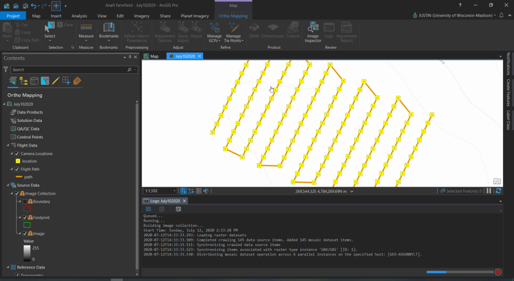
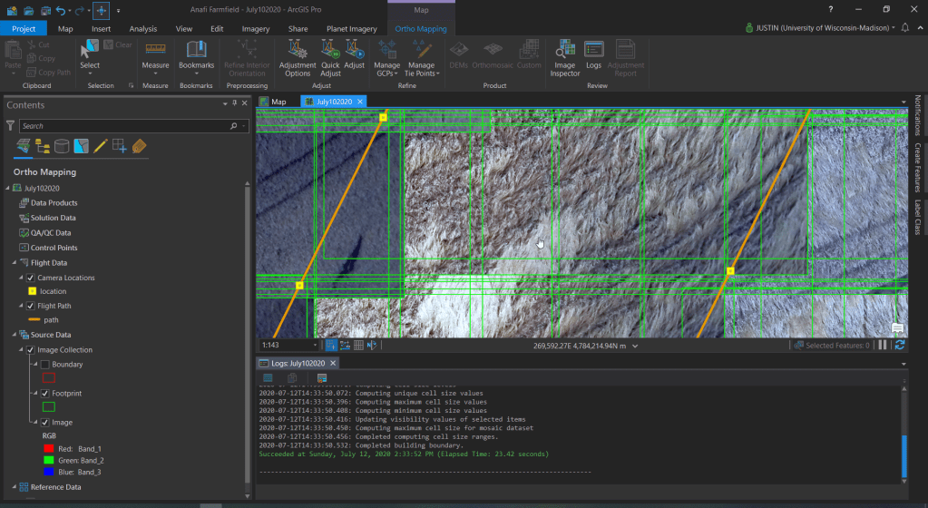
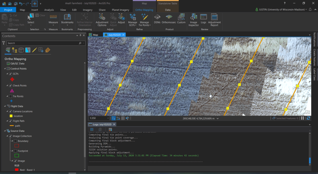
The Orthomapper workspace is a ribbon as well as a backend data structure. What you first see is the path of the UAV and then camera locations. As the images load, you will see the footprint of each image. Note: this took about 30 seconds.
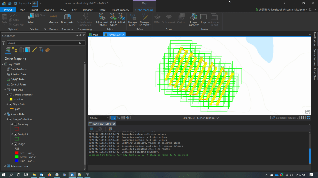
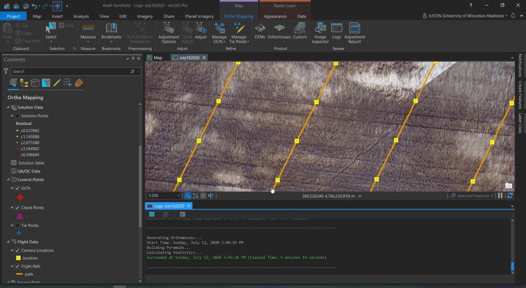
You can also zoom in and see the individual images. It will look really messy because of the overlap.
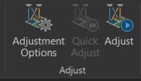
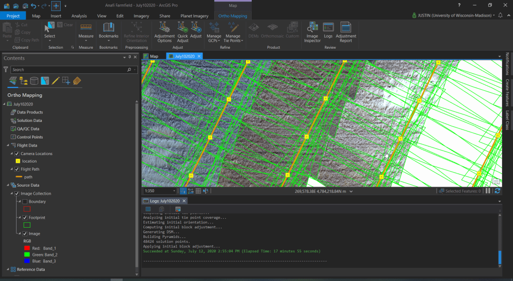
In the workspace, we can use some adjustment tools to line up the images and find tie points between them. When you are first starting up it is a good idea to do the quick-adjust first. It takes less time and will give you an idea of what you have. It will still not be perfect but it is a start. Note: this took about 15 minutes
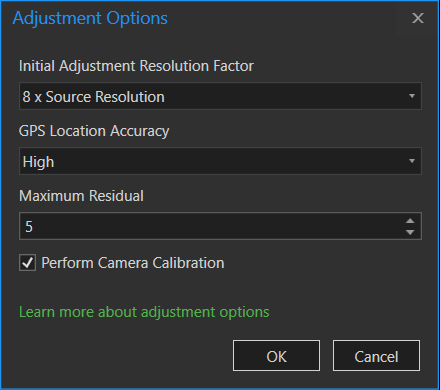
If the quick adjustments look good you can run the final adjustment tool. There are options that can be adjusted to improve the adjustments. I did not change any of the settings. When running the final adjustment this will take longer than the quick adjustment(about 40 minutes) but will be a lot better. While the adjustment will improve the alinement, it will not color match the images.
After the adjustments are done you can now create the final products of the orthomosaic and digital surface model.
Creating the Orthomosaic and Digital Surface Model
You can make one of these or using the custom button both. I ran the custom because I wanted both products.

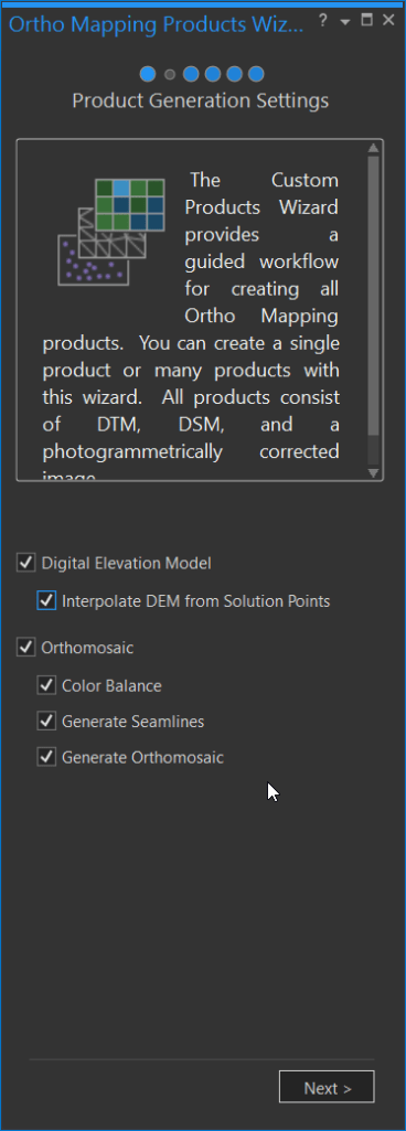
When you start the custom product settings it asks you what do you want to create. I selected all of the products. Then I hit next.
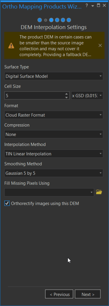
The first tool is for the digital surface model. Here you have options for cell size, format, and interpolation method. I kept most of the options the defaults to see what I get, but I did select the last box for Orthorectify images using this DEM. This option allows the improvement of the orthomosaic using the local elevation data instead of a general elevation dataset. When this option is checked you will see a message that it may be smaller than the source data. In testing I first ran with this turned off, and got some edge issues, but turning this option on gave better results. Then I clicked next.
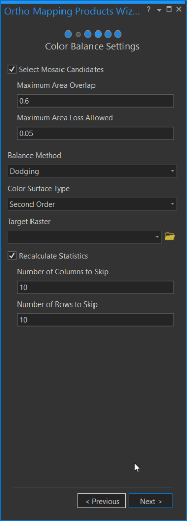
Next is the color balance setting this helps with the color matching of the images. I kept these options as default.
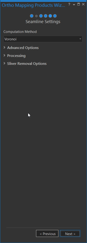
Next is the seamline settings. I have not explored these options yet.
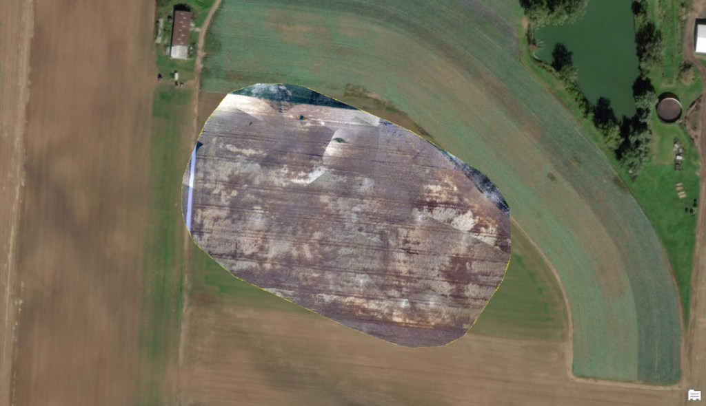
After the seamlines is the orthomosaic settings. I kept the pixel size the same and looked at the formats. After running these I planned on exporting the results anyway so I keep that the same. Then I clicked finish and let it run. The total tool took about 30 minutes.

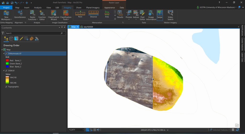
Then because I wanted to have all of the data in a project geodatabase, I exported the dem and orthomosaic. With the data in your preferred format, you can do any of the different analyses or appearance tools that you have available to you.
I hope this helps you be able to process your own UAV imagery.

Ground Control Points
I did leave out one important part and that is ground control points. To get more accuracy positional accuracy, use ground control points. In the Orthomapper Workspace, there are tools that can help you with is. During our collection, we did not take points because our main concern was to just capture some test imagery. In future collections, we will be adding this to our field collection workflow.


Ich lese Ihren Artikel mit Interesse, danke. Hilliary Byram Riancho
LikeLike